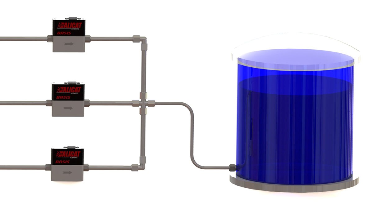
Are you familiar with the role of mass gas flow controllers (MFCs)? These instruments are widely used in industrial and laboratory environments due to their high accuracy.
There are certain basic considerations when choosing an MFC, including pressure drop, ambient temperature, reference conditions, gas type, etc. Each specification has to be analyzed attentively prior to making a decision.
If looking for a mass gas flow controller, we hope the information below is of assistance.
What is an MFC?
MFCs stand for devices used to control and measure the flow of gases and liquids. These instruments are designed, calibrated, and tested to operate under certain conditions, such as upstream pressure, downstream pressure, temperature, flow range, etc. Such devices are provided with a setpoint ranging from zero to a hundred percent of their full-scale range.
MFCs are either analog or digital. The former has limitations to the fluid for which calibration has been made, whereas the latter can control more than a single fluid type. In terms of the components, these devices are equipped with an outlet port, an inlet port, a control valve, and a mass flow sensor.
Mass flow gas controllers require the liquid or gas that’s supplied to fall under a certain pressure range. Low pressure will deprive the instrument of fluid and make it unable to reach the setpoint. Conversely, high pressure leads to inconsistent flow rates.
What to consider when choosing one?
When choosing such an instrument, the overall flow rate is of great importance to consider. Certain processes require nothing but small flows, usually expressed in SCCM (standard cubic centimeters per minute.) Conversely, higher flows are usually specified in SLPM (standard liters per minute.) The largest part of manufacturers creates these instruments to conduct measurements between 200 SCCM and 30 SLPM.
Another essential consideration is the gas itself, as the design of the instrument depends on the hazardous nature of the gas. For example, a simple design can be used if flowing a common gas, such as oxygen, air, helium, nitrogen, argon, hydrogen, CO2, or CO. Click here to get to know some useful facts about nitrogen.

In contrast, if the gas is hazardous, it might require a different treatment. In case it’s prone to contamination like when reacting with moisture, the interior of the instrument should be polished and other types of connections to be used. Instead of compressed and screwed fitting, the connections should be VCO or VCR used for high-purity gases.
Regarding pressure, some MFCsare limited to working pressures between 100 and 500 psi. Industrial models, however, are designed to withstand a pressure of up to 4500 psi.
Nevertheless, processes operating under high vacuum require MFCs to be calibrated for vacuum service. Gas temperatures should be considered as well, which is why there are temperature limits inside these instruments. Generally, the standard working limit for gases in MFCs is 140-160˚F.
Specifications
In order to gain a solid understanding of MFCs, there are certain specifications to be considered, including accuracy, repeatability, pressure drop, turndown ratio, warm-up time, span shift, etc. Let’s start with accuracy. It refers to the measurement of the precision of the instrument’s performance at different flow ranges.
Moreover, accuracy mainly depends on operating conditions, including the pressure and gas flowing within the instrument. Manufacturers tend to calculate the error rate of their controllers by basing it on standard pressure and temperature. Consequently, the unit’s accuracy might vary significantly when the operating conditions are unable to meet the specified parameters by the manufacturer. Certain instruments are equipped with interior sensors to monitor temperature and pressure and conduct corrections if necessary.
Repeatability measures the instrument’s ability to repeat flow functions accurately. It’s determined by monitoring the device’s readings, stopping the flow to enable the instrument to go back to zero, and then resuming it once again.
Conversely, the pressure drop is classified as pressure loss because of the friction between the pipe wall and fluid particles when the fluid moves through the pipe. It’s under the influence of each component that the fluid gets in touch with. Follow this URL, https://en.wikipedia.org/wiki/Pressure_drop, to learn more about pressure drops.
Turndown ratio refers to the range of these instruments between the minimum and maximum flow. Warm-up time is described as the time amount necessary for the instrument to be stable to use. Some models require half an hour to reach a stable state.
Zero shift explains how far from zero the instrument will move upon a change in pressure or temperature. Span shift, however, describes the slope’s shift of the calibration curve with no change happening at zero.
The bottom line
Make sure you understand the concept of these devices before selecting a model.
Do notrush through the process, as you need to obtain accurate and fast results!


 The $100K Skill Nobody Taught You: Prompt Engineering Explained


